Hi All:
I am working a project using an esp32 chip on a pcb design I pretty much copied from a dev board. I am new to microcontrollers but thought I could do this. When I plug in the usb, the board just keeps connecting and disconnecting. It isn’t my pc because my dev boards all work (even when plugging in a new dev board it will say either “espressif device found” or “JTAG Device found”.
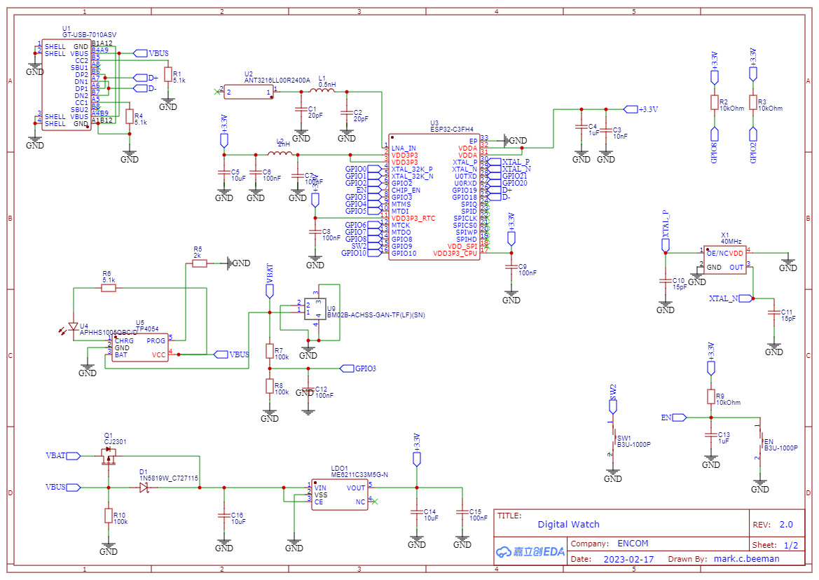
So my pc doesn’t recognize the device. The schematic is here:
No surprise - most of this I copied directly from this dev board:
https://www.wemos.cc/en/latest/_static/files/sch_c3_pico_v1.0.0.pdf
However, one thing I was wondering about. If you look at the dev board schematic, on the usb they connected VBUS to A4B9 while I connected it to both sides i.e. A4B9 and B4A9. Would that be an issue?
Any help is greatly appreciated!
Fish
Well do you measure VBUS = 5V and no short to unrelated nets? Then that’s not the problem. Is 3.3V present too at the ESP32 module?
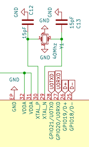
What struck me as particularly odd is your oscillator
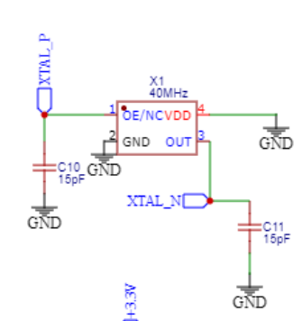
The schematic symbol of this oscillator is that you just give it power and gnd (via GND and VDD), it produces a the given 40MHz wave at the OUT pin while OE (output enable) is either active or not-connected. You have wired it up like X1 is a regular crystal, like they do in the dev kit.
I’m not sure if that’s a case of you using a very wrong schematic symbol or whether you actually have an oscillator instead of a quartz crystal on your board. If it’s an actual oscillator instead of the pure crystal, then this setup is completely wrong. See https://www.espressif.com/sites/default/files/documentation/esp32-c3_hardware_design_guidelines_en.pdf page 10, section “If you use an oscillator…”. Without a clock signal, the microcontroller won’t start up and execute code at all and so it’ll definitely not be recognized as a USB device.
1 Like
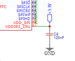
Oh and what’s up with VDD_SPI being disconnected?
vs reference
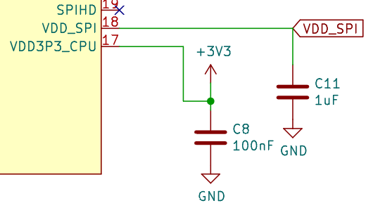
Doesn’t the internal flash chip then just get 0 power?
Edit: Hm okay per above hardware design guides that’s okay because it can either be used to power an external flash chip or be used as GPIO.
1 Like
Yes…per the esp32-c3 datasheet:
By default VDD_SPI is the power supply pin for embedded flash or external flash. It can only be used as GPIO11 only when the chip is connected to an external flash, and this flash is powered by an external power supply.
So I just didn’t connect it.
Max:
I will be honest…this is pretty embarrassing. This part did throw me when I was trying to sketch it up. I did not understand what the hardware design guide meant by:
It is also recommended that the circuit design for the oscillator is compatible with the use of crystal, in case that if there is a defect in the circuit design, users can still use the crystal.
Not knowing much about oscillators, I just assumed that if I used it like a crystal, it would operate as such. So not only am I stupid, but I get to be stupid in a forum full of very smart people .
BUT - Once again, I owe you thanks, Max.
Fish
If you’re lucky, the footprint of your current oscillator is also the same as that of the quartz crystal that should be placed there instead. So if you have a hot air gun and a 40MHz crystal of the required footprint, you could try and swap it out.
1 Like
Looking back…I think I do need to connect VDD_SPI as well.